Table of Contents >> Show >> Hide
- What an Open Source Micro-Manipulator Needs to Do
- Key Performance Words You Must Not Hand-Wave
- Three Open Source Architecture Patterns (and Why They Exist)
- Actuation Choices: Stepper, Servo, Piezo, or “All of the Above?”
- Open Source Secret Sauce: Feedback and Calibration
- Mechanical Design: Where Precision Actually Happens
- Electronics and Firmware: Keep It Replicable
- Open Source Hardware Hygiene
- A Practical Build Path: From Sketch to Stable Motion
- Common Use Cases (and Design Tips That Save Time)
- Field Notes: What Builders Learn the Hard Way (Experience Section)
- Conclusion
If you’ve ever tried to nudge a probe tip under a microscope and watched it launch past your target like it’s late for a meeting,
you already understand why micromanipulators exist. A micro-manipulator (often called a micromanipulator or micropositioner) is a
motion system that lets you position a toolneedle, micropipette, fiber, microelectrode, tiny part, sensor, or samplesmoothly and
repeatably in very small increments. “Small,” here, ranges from “hair-width” to “please stop breathing near the bench.”
The open source twist is simple and powerful: instead of being locked into a single expensive vendor ecosystem, you can build a
micro-manipulator that fits your real workflow, publish the files, and let other labs and makers improve it. Done well, open hardware
doesn’t just cut costit speeds iteration, improves reproducibility, and makes specialized tools accessible to more people.
What an Open Source Micro-Manipulator Needs to Do
Before CAD, code, or shopping carts, define your “job story.” A micromanipulator that positions an optical fiber into a laser coupler
has different needs than one that moves a micropipette for single-cell work. A good design brief includes:
- Degrees of freedom: XYZ translation is common; some builds add tilt/rotation or a tool angle holder.
- Travel range: Are you moving within a few millimeters, or do you need a larger workspace?
- Resolution vs. repeatability vs. accuracy: These are not synonyms (and confusing them is how projects become “mystery machines”).
- Stiffness and vibration behavior: If the tool flexes or chatters, your “precision” becomes interpretive art.
- Drift: Temperature, material creep, and friction can slowly move your tool even when you’re “not moving it.”
- Payload and tool mounting: Pipettes, probes, fibers, small PCBs, or sample holders all load the mechanism differently.
- Control style: Manual knobs, joystick control, scripted motion (G-code), or closed-loop servo behavior.
- Build constraints: 3D printed vs. machined, off-the-shelf rails vs. custom flexures, availability of parts, assembly skill level.
Key Performance Words You Must Not Hand-Wave
Precision positioning lives and dies by definitions. In motion systems, it helps to separate:
- Resolution: The smallest step the system can command or sense (often encoder-limited).
- Minimum incremental motion (MIM): The smallest move it can reliably execute in the real world (friction, mechanics, control loop matter).
- Repeatability: How closely it returns to the same spot across trials.
- Accuracy: How close it ends up to the “true” target coordinate.
- Drift / stability: Whether it stays put over time, especially after settling.
A micro-manipulator can have astonishing resolution but mediocre absolute accuracy if backlash, calibration, or thermal effects aren’t handled.
The good news: for many microscope workflows, repeatability and stability matter more than absolute accuracybecause you can “zero” on features
in the image and work in relative motion.
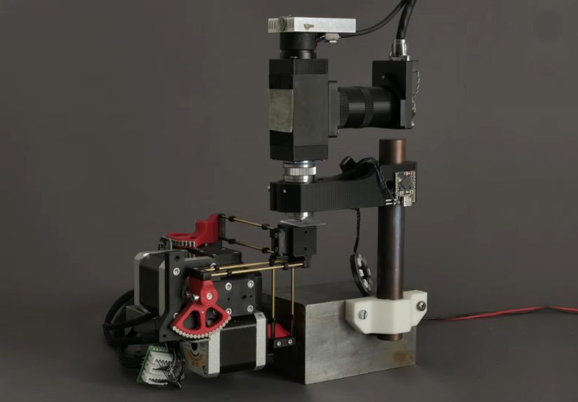
Three Open Source Architecture Patterns (and Why They Exist)
1) Nested Sliding Stages + Screws (Simple, Printable, Teachable)
A classic open-hardware approach uses multiple chassis elements that slide within one another, guided by screws (often metric) and springs.
It’s approachable, printable, and easy to repair. It can be manual (thumb screws/knobs) or motorized with continuous rotation servos and a joystick
controller. This pattern is popular in education and DIY electrophysiology because it’s intuitive: turn the screw, the stage moves.
Trade-offs: friction and print tolerances become the main “bearing system,” so expect tens-of-microns class behavior unless you’re meticulous.
Still, for positioning an electrode into a small organism or aligning a coarse tool, it can be exactly right.
2) Stacked Linear Actuators on Rails (Modular, Strong, More ‘Industrial’)
Another pattern stacks compact linear actuators into an XYZ tower. Each axis is a small linear stageoften using miniature linear rails (like MGN-style
guides) and non-captive stepper motors or lead-screw drives. It’s modular: build X, then bolt on Y, then Z. If one axis needs a different travel length,
you swap that module instead of redesigning the whole robot.
Trade-offs: rails and decent linear components add cost, but you gain stiffness and predictability. Assembly is usually more “mechanical” (squaring,
alignment, fasteners) and less “fussy with sanding printed holes until the universe forgives you.”
3) Parallel Kinematics + Flexures/Ball Joints (High Stiffness, Fancy Math, Big Smile)
Some of the most impressive open-source micromanipulators use parallel kinematic structuresmultiple arms/links moving togetheroften paired with
miniature ball joints and flexures. The mechanical advantage is stiffness: parallel kinematics can resist loads and vibration better than long
cantilevered stacks. The “software advantage” is that you can shape motion through kinematic transforms, making it easier to map motor motion into
tool-tip motion (once you’ve done the modeling and calibration).
Trade-offs: calibration and kinematics are mandatory. The build can be compact and high-performance, but it asks more from your firmware and testing.
Actuation Choices: Stepper, Servo, Piezo, or “All of the Above?”
Stepper Motors (Accessible, Predictable, Great for Open Builds)
Stepper-driven systems are common in open source micromanipulators because they’re widely available, easy to control, and friendly to modular electronics.
With a lead screw, your theoretical linear step size is:
Real-world note: microstepping increases smoothness and commanded resolution, but it doesn’t guarantee proportional torque or perfect tiny moves.
That’s why “minimum incremental motion” can be bigger than “resolution.” If your project needs truly reliable sub-micron motion, you’ll focus on
mechanics, friction management, and feedbacknot just microstepping settings.
Continuous-Rotation Servos (Fast Prototypes, Education-Friendly)
Servo-motorized printable manipulators are a great teaching tool because they reduce wiring complexity and can be driven by simple microcontroller setups.
Pair them with a joystick shield, and you have “human-in-the-loop” fine control quickly. This is often enough for coarse positioning and demonstrations.
Piezo Motors and Piezo Stages (Nanometers with Caveats)
If you need nanometer-class motion, piezo-based systems are a standard approach in commercial precision stages. Piezo motors come in multiple design families
(ultrasonic/resonant, stick-slip/inertia, and piezo-walk), each with its own speed, force, and control complexity.
In open source builds, full piezo stages can be expensive and electronically complex, but hybrid approaches are practical: use a stepper stage for coarse travel,
then a small piezo actuator for fine trimming. This split mirrors how many high-end positioning systems handle “long travel + ultra-fine adjustment.”
Open Source Secret Sauce: Feedback and Calibration
The difference between a “cute mechanism” and a “trusted instrument” is how it behaves after you build it. Two levers matter most:
feedback (knowing where you are) and calibration (mapping commanded motion to real motion).
Open Loop vs. Closed Loop
Open loop control assumes the motor’s steps equal motion. Closed loop control measures position (encoders, sensors, computer vision, etc.) and corrects errors.
In micro-manipulation, closed loop can help compensate for friction, load changes, missed steps, and mechanical tolerances. But it also demands:
stable sensing, low-noise electronics, and a control loop that won’t introduce jitter.
Calibration: The Part Everyone Skips Until It Bites Them
Calibration is where open hardware often winsbecause you can build it into the toolchain and share the workflow. Practical calibration ideas:
- Axis scaling: Verify mm-per-step (or tool-tip displacement per motor increment) with a microscope reticle or calibrated target.
- Orthogonality checks: Confirm that X doesn’t sneak into Y, and Z doesn’t add a surprise diagonal drift.
- Backlash characterization: Approach a target from both directions and measure the deadband. Compensate in software if needed.
- Thermal drift tests: Let the system sit, record tool position over time, and identify if printed parts or motors are warming things.
- Repeatability runs: Command a repeated motion pattern and quantify return-to-point scatter.
Mechanical Design: Where Precision Actually Happens
Stiffness: Short, Supported, and Not Overly Optimistic
Precision hates long levers. Keep tool mounts close to the final guidance element. If you must extend a probe, brace it. Use triangulation or parallel linkages
where possible. A stiffer structure raises your resonant frequency and reduces the “tap the table, ruin the experiment” problem.
Backlash and Compliance: The Quiet Villains
Backlash shows up in lead screws, gear trains, loose joints, and flexy printed parts. Compliance shows up in plastic deformation, thin walls, and tool holders.
For open builds, common strategies include:
- Preload: Springs or opposing nuts to keep threads engaged in one direction.
- Flexures: Replace sliding joints with controlled elastic deformation for zero-backlash motion (within limited travel).
- Better guides: Linear rails or smooth rods/bushings reduce “sticky-slip” compared to raw printed surfaces.
- Material choices: Stiffer filaments and thoughtful geometry reduce creep and drift.
Thermal Behavior: Your “Invisible Axis”
In micro-scale positioning, temperature changes are effectively another degree of freedomexcept you didn’t ask for it, and it doesn’t follow commands.
Motors warm up. Lights warm up. Hands warm up. If you 3D print structural parts, expansion and creep can become noticeable.
Designs that minimize material bulk, use stiffer structures, or separate heat sources from precision elements tend to behave better.
Electronics and Firmware: Keep It Replicable
One hallmark of strong open source lab tools is replicability: common parts, clear wiring, and firmware that doesn’t require wizard-level setup.
A practical electronics stack might include:
- Microcontroller: Something widely available (e.g., an Arduino-class board or a modern MCU board).
- Motor drivers: Off-the-shelf modules with known performance and easy replacement.
- Power: Stable, appropriately rated supply with decent grounding and cable management.
- Encoders (optional but powerful): Rotary or linear feedback for closed-loop behavior.
- Human control: Joystick, knobs, or simple UI for live operation.
G-code, APIs, and the “Make It Scriptable” Rule
If your manipulator can accept simple motion commands (like G-code) or exposes a clean serial protocol, it becomes a platformnot just a gadget.
Scriptable motion lets you:
- Run repeatable alignment routines (fiber coupling, probe landing, raster scans).
- Log moves and build reproducible protocols.
- Integrate with microscope software or computer vision for automated positioning.
- Share workflows that work across labs with the same open design.
Open Source Hardware Hygiene
“Open source” is not a vibe; it’s documentation plus licensing plus community-ready design. If you want your micro-manipulator to be buildable by someone
who doesn’t already live inside your brain:
- Publish editable CAD (not just STLs). Parametric files help people adapt the design.
- Provide a real BOM with part specs, alternatives, and notes on “what matters” (e.g., rail type, screw pitch).
- Document assembly with photos, torque notes, and alignment checks.
- Include calibration procedures and expected performance ranges.
- Choose a license that matches your goals (permissive vs. share-alike; hardware-focused licenses if desired).
- Design for substitutions (because supply chains love chaos).
A Practical Build Path: From Sketch to Stable Motion
Step 1: Pick the Architecture That Matches Your Work
If you’re building for education, rapid prototyping, or coarse positioning, a screw-driven nested stage can be perfect. If you need high stiffness and modularity,
stacked rails and linear actuators shine. If you want high performance in a compact form and you’re comfortable with calibration and kinematics, parallel designs
can be a joy.
Step 2: Define Targets (and Be Honest)
Set targets for travel range, repeatability, drift per minute, and payload. Then decide what you’ll actually measure. If you only measure “it feels smooth,”
you will eventually discover new definitions of sadness.
Step 3: Prototype the Motion Chain
Build one axis first. Validate guidance (rails/rods), drive (screw/stepper/servo), and mounting. Then replicate. Precision projects become manageable when you
modularize and test early.
Step 4: Add Control and Logging
Even if you start with manual knobs, add a way to log positions and moves. A simple serial protocol, a lightweight Python interface, or a basic UI will pay off
the moment you try to reproduce a setup.
Step 5: Calibrate, Iterate, and Publish
Calibration turns “design” into “instrument.” Publish your calibration method and real measured performance, not only the “best-case” claims.
Open source gets stronger when it includes truth-in-advertising.
Common Use Cases (and Design Tips That Save Time)
- Optical alignment (fiber/laser): prioritize smooth micro-moves, high stiffness, and minimal drift after settling.
- Probe stations / electronics probing: add stable tool holders, ESD-friendly practices, and repeatable approach angles.
- Single-cell or microinjection workflows: prioritize vibration control, gentle Z motion, and comfortable manual override.
- Microscope sample positioning: consider stacking with a stage or integrating with imaging software and focus routines.
Field Notes: What Builders Learn the Hard Way (Experience Section)
The first time you assemble an open source micro-manipulator, you’ll probably feel like a wizard. The second time you try to hit the same point twice,
you’ll feel like a wizard whose wand is made of warm spaghetti. That emotional journey is normaland it’s mostly physics, not personal failure.
Many build logs start with a triumphant “It moves!” followed by a quieter “It moves… when it feels like it.” The culprit is usually friction behavior.
Printed parts can have slightly oval holes, rails can be misaligned by a fraction of a millimeter, and screws can bind if the axis isn’t straight.
The fix is rarely dramatic. It’s a pile of small wins: reaming holes to a consistent diameter, squaring assemblies during tightening, adding a touch of
appropriate lubrication on guides (where compatible), andmost importantlypreloading screw threads so motion always “pushes” the same way.
Then comes backlash, the stealthy prankster of precision mechanics. You’ll notice it when you approach a target from the left and nail it, then approach
from the right and miss by just enough to be annoying. Builders often adapt by making approach direction a habit: always “creep in” from the same direction
for final positioning. If your firmware supports it, software backlash compensation can help, but it’s not a magic wandmechanical improvements (preloaded nuts,
tighter joints, better guides) usually deliver bigger gains.
Heat is the next surprise. Motors warm up. LEDs warm up. Even the room’s air conditioning can cycle and change temperature slowly. At macro scales you shrug.
At micro scales, the tool tip quietly drifts like it’s practicing for an escape room. Builders combat this with boring-but-effective choices: let the system
warm up before “serious” positioning; isolate heat sources; keep structural members short; use stiffer structures; and avoid leaving a motor energized at high
current unless you need holding torque. Some teams also discover that “compact” isn’t just aestheticit’s thermal strategy, because less material means less
expansion and less creep.
Cable management is another rite of passage. The manipulator itself can be perfect, but a stiff wire bundle can apply enough force to tilt an axis or create
repeatability errors. Builders who win here treat cables as mechanical elements: use flexible wire, strain relief, and routing that doesn’t tug across travel.
If you’re adding sensors or encoders, keep wiring tidy and groundednoise and jitter don’t announce themselves politely; they show up as “why is it vibrating
when nothing is touching it?”
Finally, documentation changes how the project feels. The moment you write down your calibration steps and expected performance, you start designing like an
instrument maker instead of a tinkerer. Builders often report that the “second version” is dramatically betternot because the CAD is prettier, but because
the workflow is clearer: print settings, assembly order, alignment checks, and a simple test pattern (like a repeated motion routine) that proves repeatability.
That’s the real open source superpower: the community can improve what’s measurable, shareable, and reproducibleso your micro-manipulator becomes less of a
one-off masterpiece and more of a reliable tool that others can build, trust, and extend.
Conclusion
Designing an open source micro-manipulator is equal parts mechanics, motion control, and honesty. Pick an architecture that matches your use case, define the
performance you’ll actually measure, and treat calibration and documentation as first-class features. The “open” part isn’t just publishing filesit’s making
a tool other people can replicate and improve. When you do that, you’re not only building a micropositioner; you’re building shared capability.